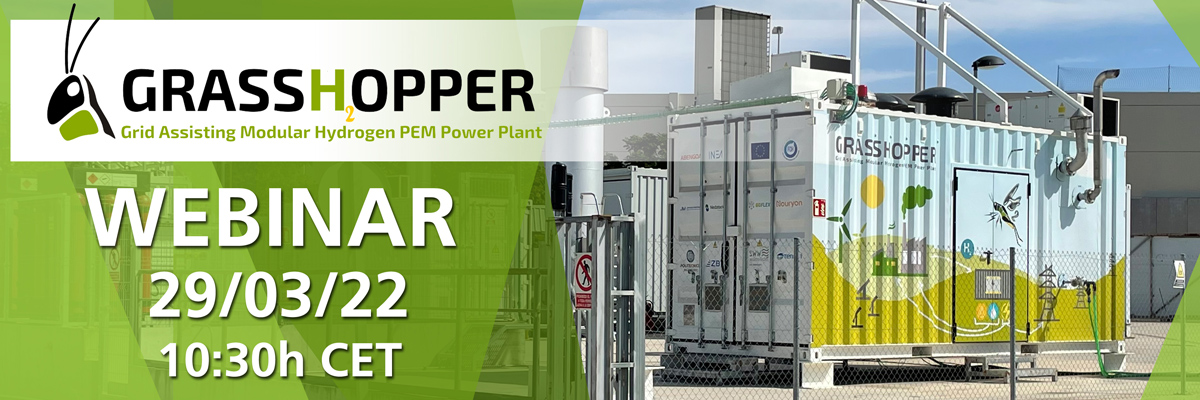
Project webinar – It is time to meet the team
After many months of hard work, setbacks and achievements, we are approaching the project end. During the last months, we have had the opportunity to present the project to some lucky groups that were able to travel to Seville and see the plant live. However, as it happened with any other aspect of our lives, covid prevents us from scheduling any live event. But there is always a bright sight! The grasshopper team has prepared a public webinar to share our learning and experience with the world. Here is a brief summary of the content you can expect in the webinar
- Overview of project goals and objectives
- Main results and achievement obtained so far
- Virtual tour to the 100 kW pilot plant
- Questions and interaction with the technical members of the project
There are limited spots, so be sure to register using the following link! Also, check out our new introductory video of the project, including a sneak peak to the pilot plant.
—> Register now here! <—-

Initial performance results on new MEA – Built To Last
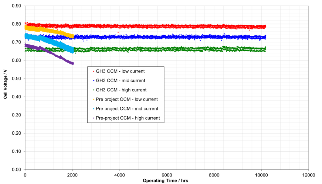
To achieve lower production costs and improve durability of Fuel Cell Power plants, it is essential to develop a new generation of MEAs (Membrane Electrode Assemblies). Johnson Matthey (JM) developed a new fuel cell membrane-electrode assembly (MEA) for a flexible, grid-supporting hydrogen power plant. To achieve the project objectives, JM’s MEA had to be durable, powerful, inexpensive and capable of flexible operation in response to changes in demand. Building on recent advances in automotive fuel cell technology and high volume manufacture at JM, it was possible to reach target manufactoring costs. Further enhancing the resulting MEA with measures to extend the lifetime.
The EU’s VOLUMETRIQ project (FCH-JU grant no. 671465) devised a drive cycle partly based on the New European Drive Cycle. A Drive Cycle is a series of data points of speed of a vehicle against time that is design to simulate the standard behaviour of vehicle. Applying it to fuel cells, the profile is transformed into current vs time. Its shape is shown below

Due to its high varibility and changing load, is a great tool to evaluate performance and degradation of the membrane with load changes. The GRASSHOPPER MEA contained a 20 μm membrane electrolyte with a reinforcement, stabilised against chemical attack. As a result, the MEA showed a very high stability in drive cycle testing. The minimal loss of performance over the lifetime of the test, combined with a period of initial performance gain during CCM conditioning over time, led to near-zero measured degradation over 10 000 hrs.

The developed MEAs are being built into stacks by GRASSHOPPER project partners Nedstack FCT, whose stacks power the 100 kW pilot-scale plant, assembled by Abengoa Innovacion. Operating the plant over its lifetime will allow us to gather real-world grid-assisting power data for this fuel cell technology.
Results. A new section of our website
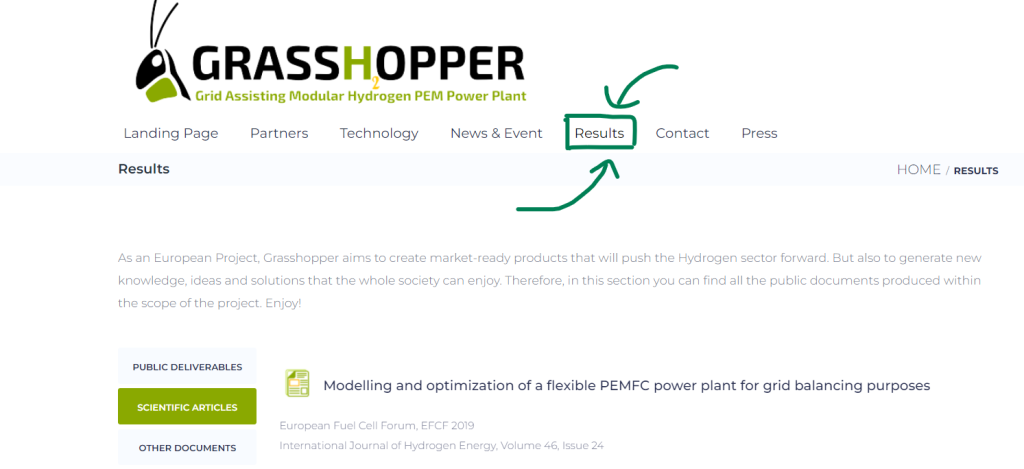
We have accumulated a good amount of results already. So its time to share them. As an European project, some of the data generated is labelled as “public”. Being our duty to make it accessible to the general population. For that purpose, we want to introduce you to the results section of the website. You can easily access it in the top menu and will allow you to download all the documents as we generate them. We distinguish between several types of document:
- Official European documentation.
- Scientific publications. Either in magazines, congress or similar
- Other interesting documents
During the last years, Politecnico di Milano, as a consortium partner, participated in the “Applied Energy Symposium: 100% Renewable” as well as other events. This particular event was a forum organised by the University of Pisa (Italy) to discuss and share the latest advancement towards a cleaner energy system. For said event, we published a paper titled: “Simulations of a flexible 100 kWel PEM Fuel Cell power plant for the provision of grid balancing services”. Where Polimi studies the potential capabilities of the pilot plant based on a computational model of the plant. This and other papers are already available in this section of the website, so keep checking it for updates!

The Pilot Plant is Doing Great! – Testing Update
It has been a while since our last update. And not because the project has stopped, but quite the opposite! We have been experiencing quite busy months since the begging of the year. At this point, we have reached the final phase of testing in Abengoa’s facilities in Seville (Spain). And in a couple of months, and if Covid-19 allows it, the plant will be installed in the final site in Delfzijl (Holland), where it will remain operating for 5 years. So, lets go into details on what have been accomplished so far.
1st testing phase completed.
During the initial months of testing, we focused on the plant itself without having the fuel cell stacks installed. In this period no power was produced, allowing us to optimise control strategies and check for improvements without worrying about damaging the delicate stacks. Many different tests were carried out including the initial commissioning and functional tests of individual equipment. Most tests fall into the category of these three main types.

As with any other plant, commissioning comes first to ensure the correct functioning of all equipment and sensors. Several steps are performed :
- Verification of correct installation and electrical connection
- Scaling of communication signals and IO testing.
- Cleaning of circuits and equipment
- First “cold” start-up of individual components and actuators such as pumps compressors, valves…
- A preliminary control loop adjustments
Once all the components have been tested individually, it is time to start the subsystem functional tests. Apart from the development of new fuel cell stacks, the project aims to design an efficient plant that protects the stacks to expand their lifespan to the maximum. Including a dynamic, fast and pressurised operation. For that, a precise control is required. Testing each subsystem before the stacks are installed is therefore critical. It allows to test without worrying about damaging the stacks.
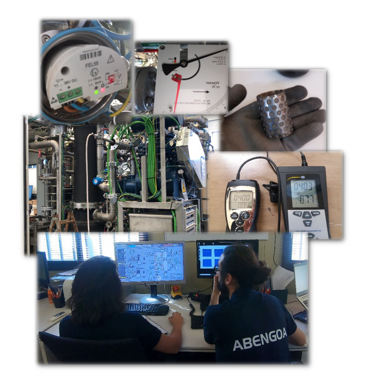
Air and Hydrogen subsystems.
Combines flow, pressure, temperature and humidity control to provide the best possible conditions of air and hydrogen to the stacks. More than 10 control loops and variables intertwine with each other. Advance control techniques such as smith predictors and multi-variable control were needed to accomplish all targets.
Cooling and utilities.
Since heat is provided by the stacks while generating power, thermal response of the plant was simulated to adjust the control. Moreover, other test were carried out as safety Nitrogen inertisation, auxiliaries consumption measurement, environmental control and anti-freezing features…
Control architecture and HMI improvements
Starting from the programming already developed during construction, a lot of effort and time has been invested into validating and updating it. With special effort on the HMI (Human machine interface), a key part of a correct plant operation.

One of the main topics that come to mind talking about Hydrogen Power Plants is safety. Hydrogen has sometimes a bad reputation of being dangerous. But, like any other fuel like natural gas or diesel, by making the adequate engineering decisions and following the safety standards created by industry experts, safe operation is assured. This is nothing new, many conventional industries have been safely working with Hydrogen since long back. And their experiences, with further innovations, are applicable to Hydrogen Power plants. In Grasshopper, safety has always been a core engineering focus, and of course, during testing even more. The safety analysis is, as a consequence, a continuous process that starts at the engineering phase, follows the construction, and finalises “as-built”.
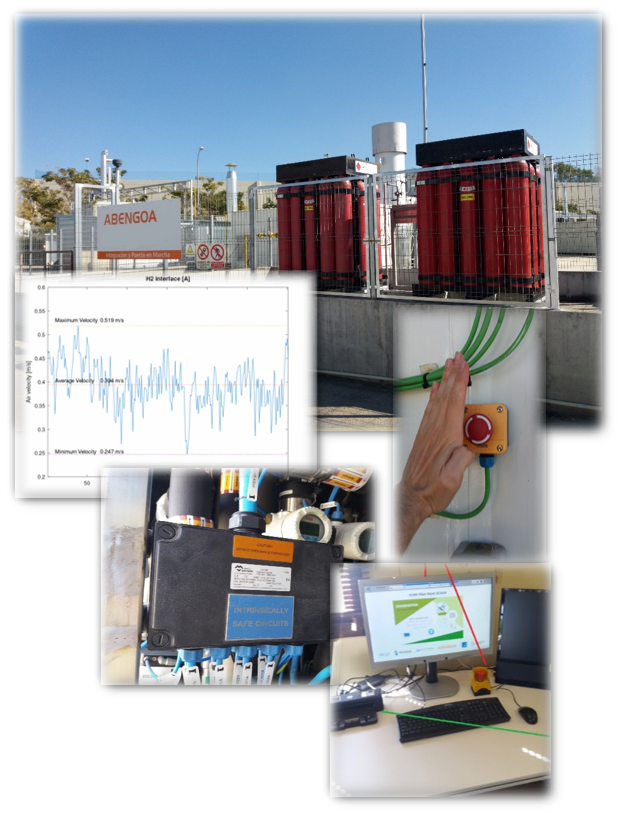
Verification of Intrinsically safe cabling and other ATEX certified equipment
Intrinsically safe instrumentation is just one of the type of ATEX certified protection available but most instrumentation and sensors are designed as intrinsically safe equipment. Which doesn’t store enough electrical energy to be a possible ignition source
Leaks detection
PEM fuel cells are permeable equipment, this means that there is an unavoidable leakage of Hydrogen around the stacks. This is usually called the stack’s “breathing”. Because of this, is very important to minimise and characterise the leakage rate of the system while the stacks aren’t installed. In any case, if anything happens that creates a hazardous atmosphere, fixed Hydrogen detectors are always monitoring the container. Additionally, hydrogen detection tape is installed around possible leak points for maintenance revisions.
Testing of emergency stops and safety subsystems
Several layers of control ensure a safe operation. Not only for personnel protection but also to minimise damage to the equipment in a “loss of control” event. If Hydrogen is detected inside the container, an emergency shutdown is performed. This eliminates any possible ignition sources maintaining ventilation. More over, the hydrogen subsystem is immediately inertised with Nitrogen.
Characterization of air renovation flow inside the container.
An interesting aspect of the safety analysis done for the Grasshopper is the study of air flow inside the container. From the beginning , the plant was designed to promote a preferential flow of fresh air that would carry any possible leaks away from potential ignition sources, quickly out of the container. During the testing phase, these initial engineering decisions were validated with a real flow analysis of the air inside the container. With over 30 points of measurement, we could characterise the air flow speed, direction and variability with ambient conditions. Creating a clear image on how the renovations of air displace and mix within the container, and where pockets of Hydrogen could potentially create when a leak occurs. It is basically like performing a “real CFD” with the plant itself.

One of the main objectives of the project is participating in the reserve electric markets. To do so, a flexible and quick response of the plant is essential. As mentioned before in the process section of this article, it is important to do so without damaging the stacks. In this initial phase, we tested the PCS (Power Conditioning System), along with all the control strategies around it. Even though the plant was not generating power from Hydrogen at this moment, the rest of the system was operating as it would with the stacks. With the help of a DC source the real response of the fuel cells was also simulated.
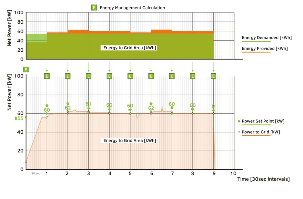
Initial results show great response both in time and accuracy, complying with the energy request with just an error of 0.25%. The control system evaluates the energy request and translates it into a power setpoint that the plant will follow. Several variables accumulate and evaluate the produced energy along time. Allowing the plant to compensate for any mismatch. In the image below a typical response of the plant can be observed. From warm stand-by, the plant immediately responds to the energy demand. The control ensures that the total amount of energy exported matches the requested.
But all of this is only but a fraction of the tests carried out in this first phase. In the following weeks we will install the fuel cell stacks in the plant and power production will begin. Starting the second phase of FAT.
Read More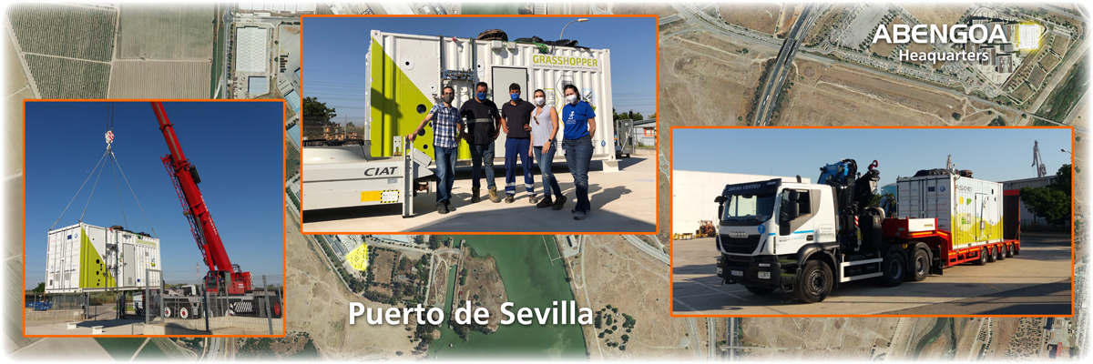
The Grasshopper pilot plant is ready for testing!
Last month, the construction of the Pilot Plant was completed! And at last, We moved it to Abengoa’s testing facilities in the port of Seville for the next phase. This is a major milestone towards the project’s success, and we are very eager to share it.
As we have mentioned before, check this post about containerized solutions, the plant can be easily transported and deployed at any location. The workshop where the plant was built was also located in Seville, so this transport only lasted about 30 mins through the outskirts of the city. But the process is identical if transported for very long distances.
Next month, Factory Acceptance Tests, or FAT for short, will begin in Abengoa’s testing facilities. Where many other technical innovation projects have also seen the light. Starting with IO Testing, following with circuit tests, or control loops adjustment among others, the pilot plant will be ready to receive the Fuel Cell stacks later this year. We will be sharing more about the FAT and how the tests are progressing along the road. For now, We hope you enjoy this video about the Grasshopper Pilot Plant transport!

Because appearance matters, take a look at our exterior design
As we have discussed in a previous post, check it out here, there are many benefits of having our power plant inside a container. But one reason that was not talked much about, is that it can be easily disguised or beautifully displayed in public. Because there are no emissions and it has a reduced footprint, placing the plant in urban areas is more than possible. and for that, the plant needs to look good!
Of course, we didn’t want to miss the opportunity to demonstrate this with the pilot plant. So we have installed a full-size vinyl that not only makes the plant look very aesthetically pleasing but also serves as publicity for Hydrogen and Green Energy sources. With a simple and cartoonish style, one can, in a glance, see the whole purpose of the project and the possible applications of the Hydrogen PEM power plants by looking at the container.

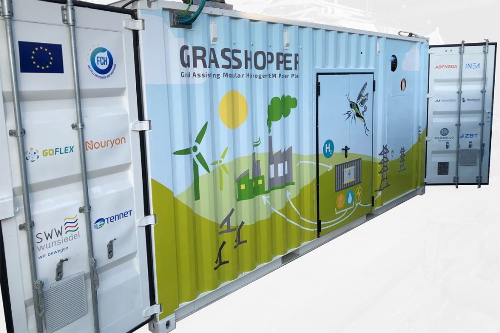
The previous images are the full design in the 3D model, first, and a real image of the container taken at the construction site prior to its completion, second. You can expect more of these pictures as the testing of the pilot plant begins in the following weeks!
Read More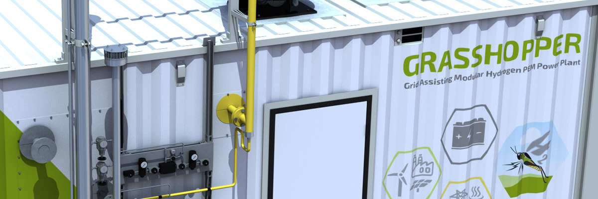
The 100kW Pilot Power Plant is under construction
As we approach the equator of the project, the construction of the 100kW pilot plant has begun. This is an important milestone for the project since many of the improvements designed on paper or laboratory scale will be tested and validated. But before we can do that, the pilot plant needs to be completed.
Like in the construction of any power plant, many different disciplines of engineering come together to create the final product. In our case, we have divided the construction into four main sections:
- Estructural: mostly regarding container refurbishment.
- Piping: equipment, instrumentation, etc.
- Electrical system: both the power conditioning system and auxiliaries.
- Control software development
With almost all engineering decisions made and 3D modeling ready, the construction can now begin. First, a standard shipping container will be modified to suit the project necessities. And once it is done, the installation of equipment and fabrication will continue until the plant is completed. Alongside the mechanical construction, the electrical system will also advance. All fitted into a 20 ft long container for rapid deployment and scalability. And lastly, the programming will put everything together, ready for a long period of testing.
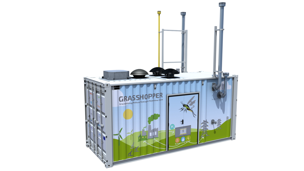
We are looking forward to receiving the first feedback directly from our workshop. Each step will surely reveal important improvements to take into account for the final MW design. We will keep you updated as things progress in our workshop with some interesting facts and news about the pilot plant construction.
Read More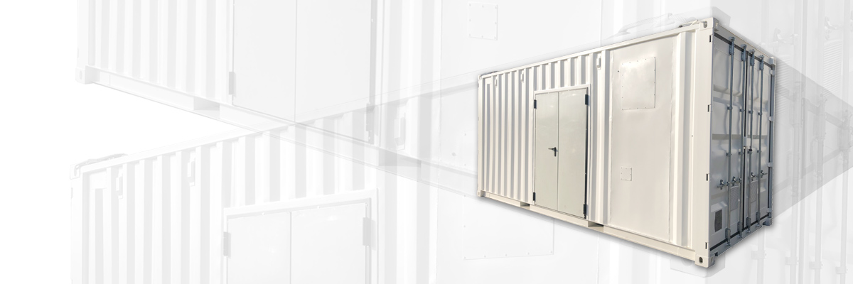
Why containerized Hydrogen Fuel Cell Power Plants make sense?
With the implementation of green energy alternatives and energy storage, there has been an increasing trend in using containerized solutions in those technologies that allow it. And not only Hydrogen PEM power plants, but many technologies have also joined this trend. One main reason for this is the great appeal of the “plug&play” philosophy, highly appreciated by the purchaser of the technology. But there is more than that for why a containerized Hydrogen Fuel Cell Power Plants make sense, and we would like to share it with you.
Scalability
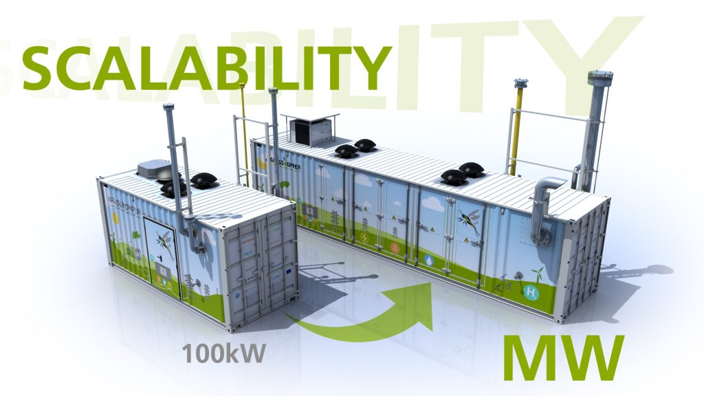
As the validation of the 100kW pilot plant finishes, We will carry out a MW scale design incorporating all the knowledge accumulated through testing. Even though the distribution of equipment inside may differ, the overall design doesn’t change much. In fact, the pilot plant has been designed for scalability. More power means increasing the number of stacks installed in the container. But since all stacks share the same design, it is a simple “copy-and-paste” process. Adding additional racks and gas distribution manifolds. Not all equipment scale at the same rate, therefore, space can be optimized with larger designs.
Modularity
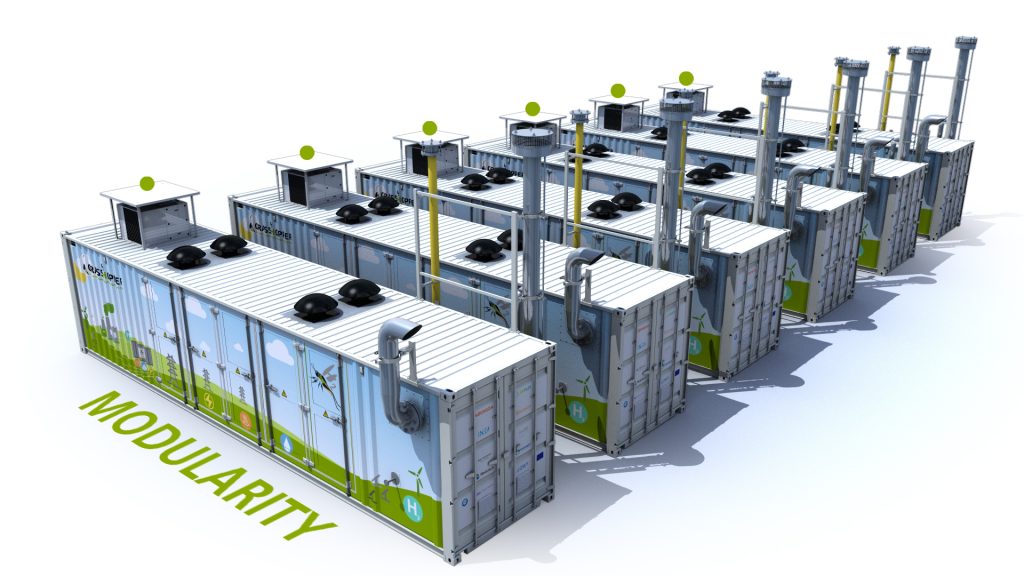
In a similar fashion, when the MW design is optimized and containerized, increasing the power of the plant is as easy as using multiple containers. Modular systems can be built, shipped, and installed quickly. This is ideal for the current increasing demand for Zero Emissions power systems. With an adequate sizing of the Hydrogen supply line and grid connection, multiplying the power is as easy as installing another container next to the previous ones. Adding a higher layer of control, adequate interaction between each unit can be achieved for maximum performance and efficiency, or maximize the lifetime of PEM stacks.
Easy transportation and Plug&Play
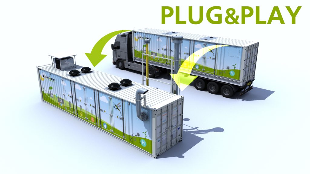
Probably the most noticeable benefit of having the plant inside a standard container is easy transportation and its quick installation. And this provides important flexibility. Containerized Hydrogen Fuel Cell Power Plants can be used in remote locations such as islands, mines, temporary buildings, encampments… Even as emergency generation units for many different applications such as data centers or hospitals. Providing a Zero emission alternative power source for such special needs. More and more of these plants are being installed in hard-to-reach places, or where the regular delivery of fuel has become prohibitive.
Not only that, but with a containerized solution, installation greatly simplifies. Forget about complex site preparations or connecting multiple units of different suppliers. Just drop the plant where you need it, connect the media and electrical interfaces and you are good to go. The electrical system, control architecture, and process, everything is packed inside. Since the container walls include these connections, no work, or minimal work, is needed inside the plant.
Transformation
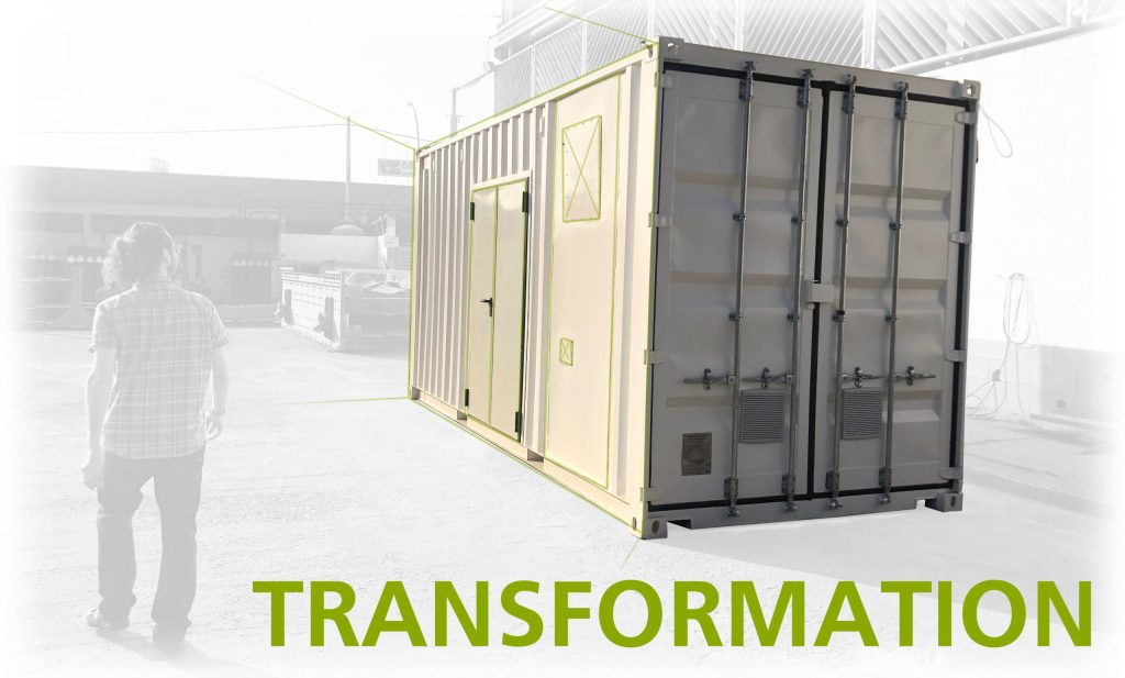
Last month, we finished the refurbishment of a standard shipping container to accommodate our needs. In the pilot plant, we have divided the container into two hermetically sealed sections. One for the electrical compartment and one for the process compartment. Media connections transverse the wall of the containers and junction boxes on the outside minimize the work inside.
The next question that arises with these units is regarding maintenance. Having all the equipment packed inside a container greatly reduces the footprint as we mentioned before, but it also reduces the available space for maintenance. This flaw can be overcome by designing an “extractable” unit. In case of a major maintenance operation, all equipment is pulled out of the container with a simple procedure. Then maintenance takes place outside.
Read More
